

DS200DTBCG1A | General Electric Contact Output Termination Module For Mark V Drive Systems
- Regular price
- $3,029.00
- Sale price
- $3,029.00
- Regular price
-
Couldn't load pickup availability

Product Description P/N: DS200DTBCG1A
Description
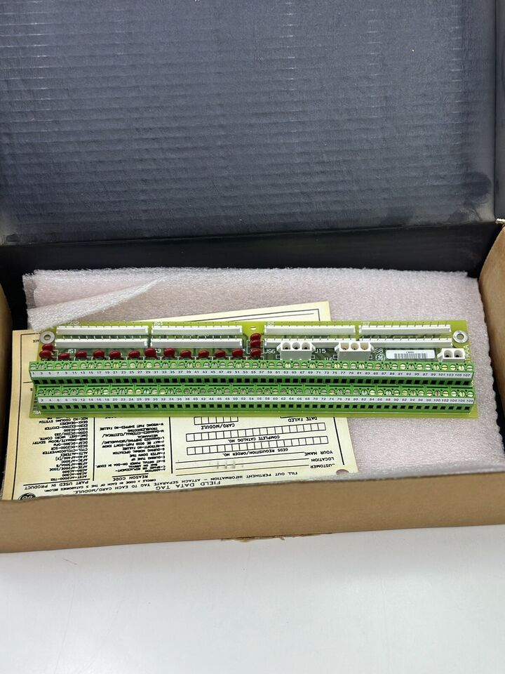
The GE DS200DTBCG1A is a Contact Output Termination Module designed for high-density signal termination within Mark V drive control systems. This board manages and routes multiple contact output signals while maintaining signal integrity through structured wiring and jumper configuration.
Technical Specifications
| Condition | New/Never Used Surplus |
| Brand | GE General Electric |
| Category | Drives |
| Part Number | DS200DTBCG1A |
| Subcategory | Drive Terminal Board |
| Series | Mark V |
| Functional Description | Contact Output Termination Module |
| Functional Acronym | DTBC |
| Functional Revision | A |
| PCB Coating | Normal coating |
| Terminal Blocks | 2 terminal blocks |
| Maximum Signal Wires | Up to 220 |
| Bayonet Connectors | 2 × 3-wire, 1 × 2-wire |
| Jumpers | 10 onboard jumpers |
| Board Dimensions | 3 in (H) × 11.5 in (L) |
| Mounting Location | Inside drive cabinet |
Information About DS200DTBCG1A
The DS200DTBCG1A is a contact output termination module manufactured by GE General Electric for the Mark V Speedtronic drive platform. It is designed to terminate and distribute a large number of output signals using dual terminal blocks and bayonet-style connectors. The board supports structured wiring layouts to reduce electrical interference and improve signal accuracy. It is installed within Mark V drive cabinets where careful wire routing and noise mitigation are required for dependable system operation.
Key Features
- High-density output termination: Supports up to 220 contact output signal wires across two terminal blocks.
- Dual terminal block layout: Provides organized and clearly defined wiring points for output signals.
- Bayonet connector support: Includes multiple bayonet connectors for flexible signal interfacing.
- Jumper-based configuration: Ten onboard jumpers allow controlled signal routing and configuration.
- Noise-sensitive installation design: Supports separation of signal wiring from power cables to reduce interference.
- Compact mounting footprint: Sized for efficient installation inside Mark V drive enclosures.
- Mark V compatibility: Engineered specifically for GE Speedtronic Mark V drive control systems.
The DS200DTBCG1A delivers the reliability and precision required for high-capacity contact output termination and signal management in GE Mark V industrial drive systems.
Description
The GE DS200DTBCG1A is a Contact Output Termination Module designed for high-density signal termination within Mark V drive control systems. This board manages and routes multiple contact output signals while maintaining signal integrity through structured wiring and jumper configuration.
Technical Specifications
| Condition | New/Never Used Surplus |
| Brand | GE General Electric |
| Category | Drives |
| Part Number | DS200DTBCG1A |
| Subcategory | Drive Terminal Board |
| Series | Mark V |
| Functional Description | Contact Output Termination Module |
| Functional Acronym | DTBC |
| Functional Revision | A |
| PCB Coating | Normal coating |
| Terminal Blocks | 2 terminal blocks |
| Maximum Signal Wires | Up to 220 |
| Bayonet Connectors | 2 × 3-wire, 1 × 2-wire |
| Jumpers | 10 onboard jumpers |
| Board Dimensions | 3 in (H) × 11.5 in (L) |
| Mounting Location | Inside drive cabinet |
Information About DS200DTBCG1A
The DS200DTBCG1A is a contact output termination module manufactured by GE General Electric for the Mark V Speedtronic drive platform. It is designed to terminate and distribute a large number of output signals using dual terminal blocks and bayonet-style connectors. The board supports structured wiring layouts to reduce electrical interference and improve signal accuracy. It is installed within Mark V drive cabinets where careful wire routing and noise mitigation are required for dependable system operation.
Key Features
- High-density output termination: Supports up to 220 contact output signal wires across two terminal blocks.
- Dual terminal block layout: Provides organized and clearly defined wiring points for output signals.
- Bayonet connector support: Includes multiple bayonet connectors for flexible signal interfacing.
- Jumper-based configuration: Ten onboard jumpers allow controlled signal routing and configuration.
- Noise-sensitive installation design: Supports separation of signal wiring from power cables to reduce interference.
- Compact mounting footprint: Sized for efficient installation inside Mark V drive enclosures.
- Mark V compatibility: Engineered specifically for GE Speedtronic Mark V drive control systems.
The DS200DTBCG1A delivers the reliability and precision required for high-capacity contact output termination and signal management in GE Mark V industrial drive systems.