


DS200TBCAG1A | GE RTD termination module for Mark V turbine control systems
- Regular price
- $3,825.00
- Sale price
- $3,825.00
- Regular price
-
Couldn't load pickup availability

Product Description P/N: DS200TBCAG1A
Description
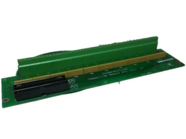
The General Electric DS200TBCAG1A is an RTD Termination Module designed for the Mark V turbine control platform. It provides secure and accurate termination for resistance temperature detector signals used in industrial temperature monitoring. Engineered for reliability, the module ensures stable signal processing in demanding control environments.
Technical Specifications
| Condition | New/Never Used Surplus |
| Brand | General Electric |
| Category | PLCs/Machine Control |
| Part Number | DS200TBCAG1A |
| Subcategory | PC Board PLC/Add-On Board |
| Product Series | Mark V |
| Functional Description | RTD Termination Module |
| Functional Abbreviation | TBCA |
| PCB Coating Type | Normal Coating |
| Functional Revision | A |
Information About DS200TBCAG1A
The DS200TBCAG1A is an RTD Termination Module built for GE’s Mark V series, designed to support precise temperature input processing within turbine and industrial control systems. As part of the PC Board PLC/Add-On Board family, it features a dedicated layout for interfacing RTD sensors and routing clean, conditioned signals to the PLC. Constructed with normal PCB coating, the module is protected against dust, moisture, and general environmental exposure, ensuring long-term stability. Designed for integration into Mark V architectures, the DS200TBCAG1A offers dependable termination performance that supports accurate monitoring and temperature-based control across critical industrial applications.
Key Features:
- RTD input termination: Enables precise connection and processing of temperature detector signals.
- Mark V series compatibility: Designed for seamless integration into GE turbine control systems.
- Normal PCB coating: Provides protection against environmental contaminants for long-term reliability.
- Clear connection layout: Labeled terminals support fast and accurate wiring during installation.
- Stable signal conditioning: Ensures consistent accuracy for temperature-dependent control processes.
- Industrial-grade construction: Withstands demanding operating environments with minimal maintenance.
- Revision A design: Delivers the baseline functionality of the TBCA termination module.
The DS200TBCAG1A delivers the reliability and precision required for accurate sensor interfacing in turbine and industrial control applications.
Description
The General Electric DS200TBCAG1A is an RTD Termination Module designed for the Mark V turbine control platform. It provides secure and accurate termination for resistance temperature detector signals used in industrial temperature monitoring. Engineered for reliability, the module ensures stable signal processing in demanding control environments.
Technical Specifications
| Condition | New/Never Used Surplus |
| Brand | General Electric |
| Category | PLCs/Machine Control |
| Part Number | DS200TBCAG1A |
| Subcategory | PC Board PLC/Add-On Board |
| Product Series | Mark V |
| Functional Description | RTD Termination Module |
| Functional Abbreviation | TBCA |
| PCB Coating Type | Normal Coating |
| Functional Revision | A |
Information About DS200TBCAG1A
The DS200TBCAG1A is an RTD Termination Module built for GE’s Mark V series, designed to support precise temperature input processing within turbine and industrial control systems. As part of the PC Board PLC/Add-On Board family, it features a dedicated layout for interfacing RTD sensors and routing clean, conditioned signals to the PLC. Constructed with normal PCB coating, the module is protected against dust, moisture, and general environmental exposure, ensuring long-term stability. Designed for integration into Mark V architectures, the DS200TBCAG1A offers dependable termination performance that supports accurate monitoring and temperature-based control across critical industrial applications.
Key Features:
- RTD input termination: Enables precise connection and processing of temperature detector signals.
- Mark V series compatibility: Designed for seamless integration into GE turbine control systems.
- Normal PCB coating: Provides protection against environmental contaminants for long-term reliability.
- Clear connection layout: Labeled terminals support fast and accurate wiring during installation.
- Stable signal conditioning: Ensures consistent accuracy for temperature-dependent control processes.
- Industrial-grade construction: Withstands demanding operating environments with minimal maintenance.
- Revision A design: Delivers the baseline functionality of the TBCA termination module.
The DS200TBCAG1A delivers the reliability and precision required for accurate sensor interfacing in turbine and industrial control applications.